A Deep Dive Into The Heart of Toyota's Hybrid System


Channel: The Car Care Nut
Uploaded by The Car Care Nut on 20260725
Categories: Autos & Vehicles
Tags: the car care nut, car care nut, tccn automotive, toyota hybrid, how toyota hybrid work, inverter, toyota, toyota reliability, toyota problems, toyota hybrid reliability, reliability, car, lexus, lexus hybrid, best toyota hybrid, how hybrids work, car review, toyota rav4 2026, should you buy a toyota hybrid
A Toyota Hybrid specialist explains exactly how Toyota's hybrid system magic happens. We take a deep dive into Toyota's Hybrid system main component which is the inverter with converter assembly. Discussing what components it has, How they work and what are some considerations of repair with this system. I hope this video makes c

Deep Dive: Inside Toyota’s Hybrid Inverter/Converter Assembly

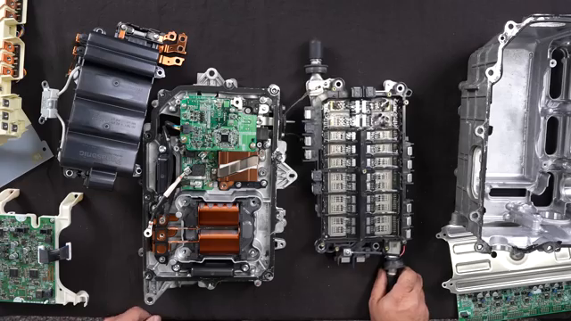
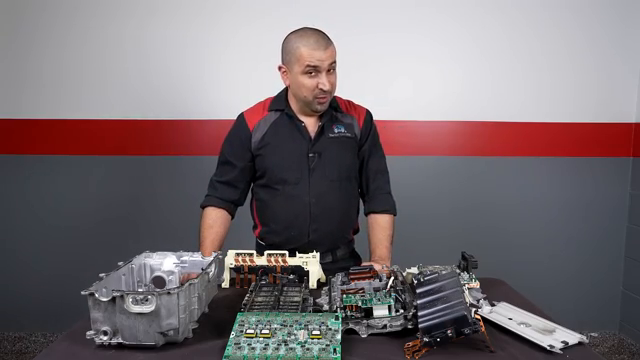
In a detailed technical teardown, The Car Care Nut breaks down the core component behind Toyota’s hybrid technology: the Inverter with Converter Assembly from a 3rd Generation Toyota Prius [03:07].

While the hybrid battery and motor-generators perform the heavy lifting, neither can function without this unit [00:25]. It acts as the operational brain and power distribution center for the entire hybrid powertrain [00:17].

Watch the full video on YouTube: A Deep Dive Into The Heart of Toyota's Hybrid System

Key Components Inside the Inverter Assembly

Component Primary Function

MG ECU (Motor Generator Control Unit) Master computer governing all inverter/converter operations and switching logic [
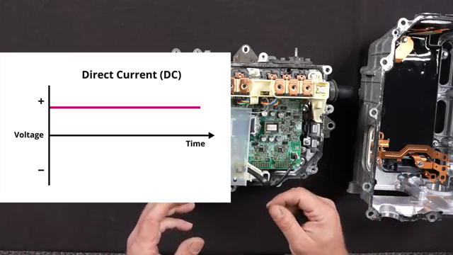
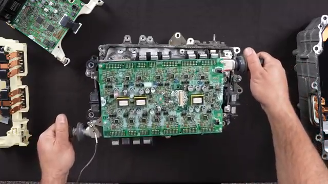
Image for chunk 1

01:12].

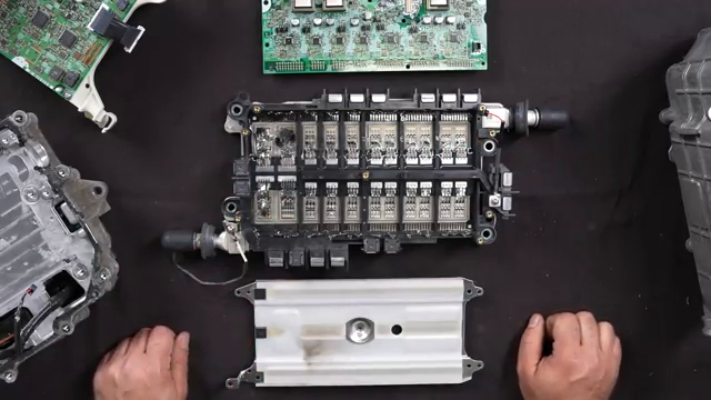
IPM (Intelligent Power Module) Converts DC power to 3-phase AC for motors and AC to DC for battery charging [01:21].

Boost Converter & Reactor Steps up hybrid battery voltage (~200V DC) up to 650V DC for motor power [01:49].

DC-to-DC Converter Replaces the traditional alternator by stepping high voltage down to ~14V DC for vehicle electronics [01:30].

High-Voltage Capacitor & Resistor Stores up to 650V DC boost charge and safely bleeds power down to 0V upon shutdown [13:44].

1. The Motor Generator ECU (MG ECU)

The MG ECU sits near the top of the internal assembly [05:10]. It continuously processes inputs from vehicle sensors—including current sensors on the motor phase leads, five internal temperature sensors on the IPM module, two secondary th

Image for chunk 2

ermal sensors, and an onboard atmospheric pressure sensor [02:04]. Based on these inputs, it commands the high-power switching modules [05:27].

2. The Intelligent Power Module (IPM) & Failure Analysis

The IPM is responsible for bi-directional energy conversion [06:02]:

DC to AC (Driving): Converts DC current from the high-voltage battery into 3-phase AC current to power Motor Generator 1 (MG1) and Motor Generator 2 (MG2) [06:37].

AC to DC (Regen & Charging): Converts 3-phase AC generated by braking or engine drag back into DC to charge the traction battery [06:18].

How the Switching Works

DC to AC: Insulated Gate Bipolar Transistors (IGBTs) switch on and off rapidly to simulate an AC sine wave [08:44].

AC to DC: Internal power diodes clip the negative

Image for chunk 3

portion of incoming alternating sine waves to produce clean direct current [09:49].

Thermal Management & Failure Modes

Because IGBTs generate extreme heat, the underside of the IPM uses specialized thermal paste mated to a dedicated liquid-cooling plate linked to the inverter coolant loop [07:11]. In the featured failed unit, extreme heat caused a catastrophic arc-over, melting several internal IGBT transistor legs and burning through the protective heat-dissipating gel layer [10:30].

3. Boost Converter & High-Voltage Safety Architecture

Voltage Boosting (Up to 650V DC)

The assembly houses a large inductive reactor coil connected to IGBT switches [12:47]. By rapidly energizing and collapsing the electromagnetic field inside the coil, the system creates

Image for chunk 4

an electromotive force that steps battery voltage up to 650V DC [13:24]. This energy is stored in a heavy-duty Panasonic film capacitor before supply to the motor circuits [13:44].

Safety Systems & Redundancy

Discharge Resistor: Because 650V DC stored in the capacitor poses a severe hazard, a built-in safety resistor acts as a continuous load [14:22]. The moment the ignition turns off, the resistor drains residual high voltage down to 0V within seconds [14:42].

Insulation Resistance (Mega-Ohm) Monitoring: The MG ECU constantly measures electrical resistance across all orange high-voltage cables [24:06]. If it detects even minor insulation degradation or current leakage to the chassis, it immediately isolates the system to prevent electrical shock [23:

Image for chunk 5

52].

4. Power Flow Dynamics: MG1 to MG2

Toyota's hybrid system utilizes two main motor-generators:

MG1: Starts the internal combustion engine and generates electricity [03:34].

MG2: Primary drive motor assisting traction and performing regenerative braking [03:34].

When MG1 generates power while the vehicle is driving, electricity is not fed directly to MG2 as raw AC [17:25]. Instead, the inverter rectifies MG1's output to DC first, then converts it back into precisely regulated 3-phase AC for MG2 [17:34]. This extra conversion stage allows fine control over power delivery and torque matching [17:46].

5. Practical Repair Considerations & Diagnostics

High-Definition Diagnostics: The MG ECU generates precise diagnostic trouble codes pinpointing individua

Image for chunk 6

l sub-circuit or sensor failures rather than general fault warnings [20:03].

Serviceability: Certain components—such as the IPM, MG ECU, and current sensors—are individually replaceable using official service kits [05:04].

Repair Complexity vs. Replacement: Rebuilding an inverter requires splitting sealed cases with specialized alignment tools, applying precise thermal grease templates, and strictly adhering to torque specifications to prevent micro-arcing [22:05].

Cost Factor: While replacing a failed IPM alone is cost-effective [27:10], cascading failures requiring the IPM, MG ECU, and current sensor often put part costs within ~$300 of a complete, brand-new assembly [26:52].

A Deep Dive Into The Heart of Toyota's Hybrid System

The Car Care Nut · 99K

No image available for chunk 7

Viewer Discussion & Comments

@stanattaphia24
The thing that gets me most about the Toyota Hybrid Synergy Drive is all the components that it doesn't need: clutch, gearbox, alternator, starter motor, flywheel. AC compressor / power steering / water pump belt drives. It's not a complication. It's a genius level simplification.
@omarsultan484
This is by far the most informative and fun automotive channel on youtube. Been a subscriber for a long time and i really respect the work ethic and dedication of this gentleman.
@JimboJason
We need more mechanics like the car care nut. He seems like he has a real passion for his job, and taking care of his customers.
@edp128128
some people think the Mona Lisa is a work of art, Ahmed thinks the hybrid inverter box is a work of art :)
@foxlake6750
My inverter failed in our Highlander, the dealer advised a new inverter was $10,000, basically making the vehicle a write off. The dealer would not consider using a used inverter. I had the vehicle towed to a friend’s shop, where we installed a used converter for $2,000. That was 5 years ago and it’s still running great. Everyone worries about the battery, but the inverter is the real killer.
@alanmarshall2103
It’s absolutely mind boggling the amount of knowledge you have as a mechanic and the simplicity in the way you deliver that knowledge to the general public. There’s no doubt that you love what you do. I could watch an hour long video of you explaining something i have no interest in and actually enjoy watching.
@_Va-Dim_
I've said it before and I'll say it again: you are the best mechanic, technician, reviewer...! The level at which you show, repair, explain everything in detail... is simply incredible! Thank you very much for everything you do!
@YT98765
I think this video cured me from thinking I’m gonna be doing any DYI fix on the inverter/converter
@JWL-UK
As an electronics engineer working with critical systems, this was a joy to watch and share with my colleagues! Thank you
@anthonyrossignol5155
Hello the reason you cannot exactly use ac from one motor to drive another is that they dont have the same frequency nor amplitude (different speed of the motors). So you harness the power of one by concerting to dc and then you can properly regenerate the three phases with the proper frequency, amplitude and phase that are required by the other motor.
@bobkozlarekwa2sqq59
I recently retired from a 45 year career with Panasonic. Part of that time was spent with the components division. You are obviously a master mechanic, and in my opinion, you’ve done an outstanding job explaining a very intricate electronic process in simplified language. BTW, my wife and I have been Toyota
@johnannison8286
Ahmed congratulations, what a great presentation. I am a retired electrical power systems engineer and particularly impressed of how Toyota managed just the mechanical/thermal issues, let alone the power generation/conversion, monitor, and computer systems.
@RobertD-l2o
As a retired PCB Designer and Component Librarian, this is treat. Thank You
@davidshettlesworth1442
Wow! I have a lot of respect for Toyota engineers. They sweat the small stuff.
@aj8991
Thank you for taking the time to show us how this works!